Part 1 — Why Compare Paths to a Reliable Interpretation System
We begin with a clear view. At a multi‑track summit, eight languages share one stage, and the clock ticks on every word. An interpretation system converts live speech to parallel channels with near-zero drift. Now imagine 600 delegates, 40 booths, and three overflow rooms. The data is simple: if the latency budget creeps past 250 ms and channel isolation drops by 3 dB, comprehension falls fast. So—how do we keep it steady when rooms, people, and RF change by the hour?

Consider the real scene: presenters walk, panels interrupt, remote guests call in, and streams go to press. The load shifts minute by minute (yes, even in perfect rooms). Infrared channels fight sunlight spill. RF links hit congestion. DSP routing grows complex, and microphones hand off between antennas. — funny how that works, right? The question is sharp: do we tweak devices one by one, or do we design the whole path as one disciplined system with clear guardrails, redundancy, and testable outcomes?
We will compare choices by their failure modes, not only by their features. Then we move from symptoms to structure.
Part 2 — The Hidden Frictions in Translation Workflows You Do Not See
Where do delays really come from?
Here is the direct truth. A conference translation device is only as strong as the path around it. Look, it’s simpler than you think. Most trouble is not in the booth at all. It hides in small handoffs: uneven gain staging into the DSP mixer, mismatched codec settings between rooms, and unmanaged VLANs that break multicast QoS. Each step adds a few milliseconds. Add them up and you lose rhythm. Add one more hop and interpreters start to chase the speaker, not lead them. That is why people complain about “echo feel,” not only “lag.”
Traditional fixes focus on the last box. Swap a transmitter. Bump power. But the flaws live upstream. Power splitters stretch PoE limits. Redundant topology is not actually redundant. RF congestion comes from house AV and media crews who did not share a plan. Even cable paths create micro dropouts when connectors loosen under traffic. In short, the chain fails where no one looks. Better principles help: define a hard latency budget per segment, protect channels with AES‑128 encryption, and isolate interpretation buses from paging paths. Then test with load, not with empty rooms.
Part 3 — From Hardware-Heavy to Cloud-Smart: What Changes Next?
What’s Next
The near future brings new patterns, and they are practical. Edge computing nodes will sit near booths and handle pre‑mix, noise gating, and packet shaping before audio hits the core. This cuts jitter where it starts. Smart antennas add beamforming to stabilize handhelds when rooms overflow. And hybrid links let you fail over between infrared and RF without a click. In many halls, conference interpreting equipment will negotiate profiles on the fly—codec, bit rate, and channel map—based on measured noise and occupancy (not guesses). The goal is steady speech, not peak spec sheets.
Compare this with the older model. We once threw more hardware at the wall: bigger amps, more repeaters, more power converters. It worked, until it did not. A clearer approach is systemic: measure end‑to‑end delay, verify channel crosstalk, and enforce multicast QoS at the switch, not at the rack. This is not hype; it is method. Set acceptance tests before the show and rehearse with real audience noise. If you can hold 0.2 s mouth‑to‑ear, keep channel leakage under −70 dB, and maintain stable gain across roaming mics, the rest follows — funny how that works, right?
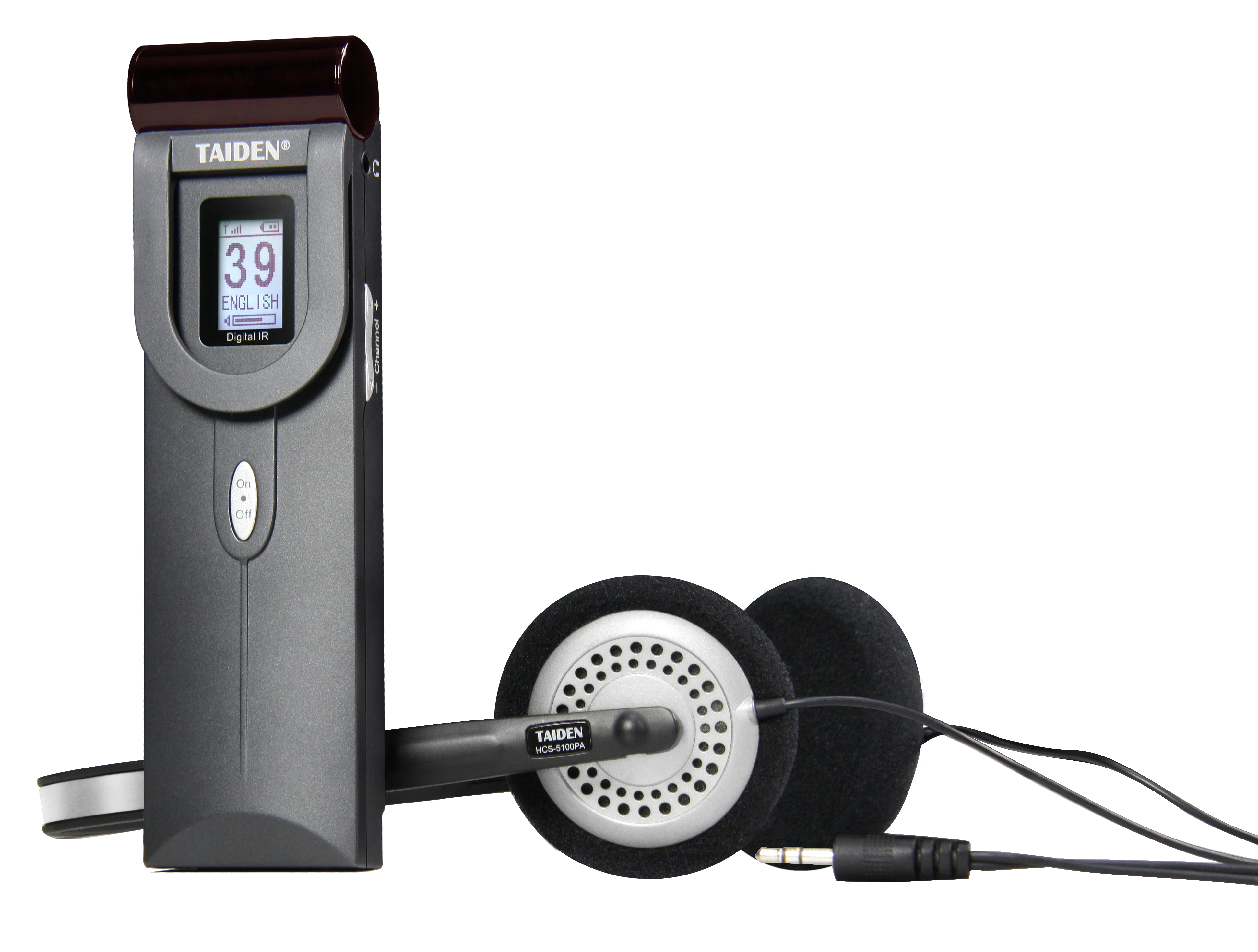
Advisory close—three metrics to guide your choice: 1) Proven latency ceiling under full load, including failover; 2) Channel integrity, measured as isolation and error rate across infrared and RF paths; 3) Operational resilience, shown by redundant topology, clear QoS policy, and health alerts you can act on in minutes. With these, you compare offers by outcomes, not by adjectives. For steady rooms and calmer crews, that is the difference that counts. TAIDEN